Air Gap in Magnetic Circuits: Theory, Practical Implications, and Flux Fringing Effects
This article reviews the role of the air gap in magnetic circuits, including its influence on magnetic relucta…
3 min read

In this article
This article reviews the role of the air gap in magnetic circuits,
including its influence on magnetic reluctance, energy storage,
inductance, and practical applications such as rotating machines,
inductors, and transformers. We analyze flux fringing phenomena and
correction factors commonly used in engineering practice. Clarifications
and corrections are provided where assumptions in the referenced source
may be approximate or context-dependent.
1. Introduction
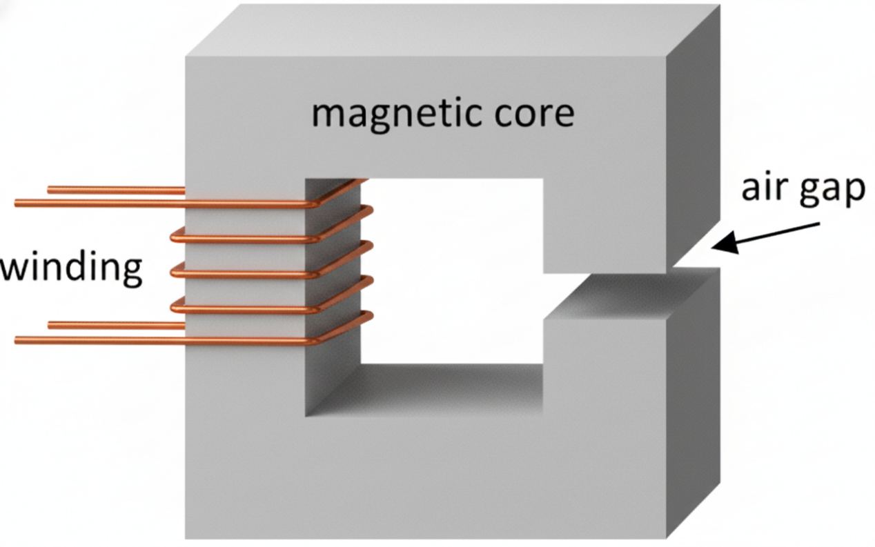
An air gap is the non-magnetic portion of a magnetic circuit
through which magnetic flux must pass, typically introduced either by
design (e.g., in gapped inductors) or by necessity (e.g., the
rotor-stator gap in motors).
Despite the common phrase “air,” the gap can be filled with any
non-magnetic medium (e.g., vacuum, plastic, water) with permeability
close to μ₀.
2. Magnetic Reluctance and Permeability
2.1 Reluctance Model
In a magnetic circuit, the total reluctance ℜ is the sum of core
reluctance ℜc and gap reluctance ℜg:
$$\mathcal{R =}\frac{l_{c}}{\mu_{c}A_{c}} + \frac{l_{g}}{\mu_{0}A_{g}} $$
Where:
-
lc, Ac:
magnetic path length and area of the core -
lg, Ag:
air-gap length and area -
μc:
permeability of the core -
μ0:
permeability of free space
Even a small air gap significantly increases total reluctance because
μ0 < < μc.
⚠ Note: The original referenced page implies changes
in B–H loop without presenting explicit reluctance formulas; therefore
this standard circuit formulation is integrated here for completeness
and engineering accuracy.
3. Effective Permeability and B–H Behaviour
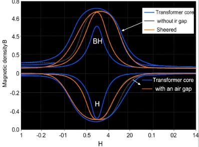
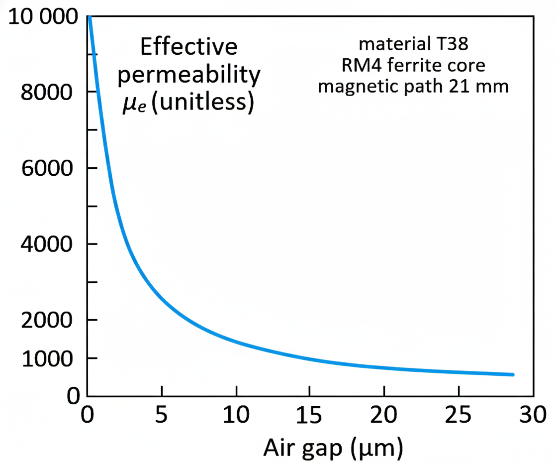
Introducing a gap reduces effective permeability, which manifests as
a lowered slope (apparent “shearing”) in the B–H characteristic. Even
minimal gaps in high-permeability cores (e.g., ferrite) can change
measured permeability significantly.
Typical manufactured gap lengths:
-
Precision ground/lapped ≈ 1 μm
-
Standard ground ≈ 10 μm
-
Purposefully gapped > 10 μm
These values are empirical estimates; exact effects depend on
geometry and material.
4. Applications of Air Gaps
4.1 Rotating Machines
Air gaps are mechanically unavoidable in rotating machines (e.g.,
motors) and lead to increased magnetizing current and lowered flux
density. Practical minimum gaps for industrial machines are typically on
the order of ~0.2 mm.
⚠ Uncertainty: The 0.2 mm figure depends on machine
size and design; values for specific machines should be specified from
manufacturer data.
4.2 Linear Motors
Linear motors require larger air gaps due to manufacturing
tolerances. Maglev trains can exhibit gaps as large as 13 mm
(electromagnetic suspension) or 102 mm (electrodynamic suspension).
4.3 Gapped and Air-Cored Inductors
Air gaps are critical in energy-storing inductors:
-
Increased gap → reduced inductance → need for more turns
-
Larger gap → higher energy storage before core
saturation -
Distributed gaps reduce fringing and loss
4.4 Transformers
Conventional transformers avoid air gaps to maximize flux transfer
and minimize magnetizing current. Any air-gap increases magnetizing
current and leakage inductance, reducing efficiency. Laminations are
assembled in overlapping patterns to minimize localized gaps.
5. Flux Fringing
5.1 Phenomenology
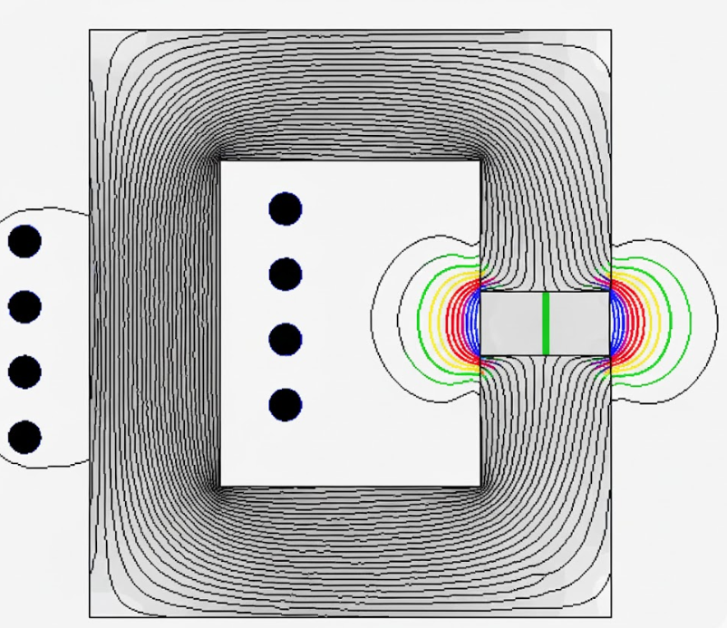
Flux fringing occurs because the air gap has much higher reluctance
than the core, causing flux to spread outward to minimize the
magnetomotive force drop. This increases effective cross-sectional area
and slightly lowers total reluctance.
5.2 Correction Factors
Empirical fringing factor models include:
$$F = 1 + \frac{l_{gap}}{\sqrt{A}}\ln\left( \frac{2l_{window}}{l_{gap}} \right)$$
Other approximations use rectangular core dimensions. These are
approximate and valid only when lgapis
much smaller than core dimensions.
6. Summary and Discussion
Air gaps are fundamental in magnetic design, influencing reluctance,
saturation behavior, energy storage, and losses. Engineering models
often require empirical correction for flux fringing and careful
geometric assumptions. Some values cited (e.g., industrial minimum
air-gap) are context specific and should be verified for each
application.
7. References
-
S. Zurek, Air gap, Encyclopedia Magnetica.
-
Flux fringing factor equations, Encyclopedia Magnetica.
-
Standard magnetic circuit formulas, engineering
references.