Low-Voltage Power Transformers: Theory, Design, Applications and International Efficiency Standards
A complete reference for transformers from 110 V to 1000 V: core and winding materials, thermal life, K-factor for non-linear loads, autotransformers, CTs, vector groups, per-unit calculations, voltage regulation and the MEPS rules in six regions.
14 min read
In this article
- 1. Transformer Basics
- 2. Construction and Materials
- 3. Transformer Loading
- 4. Multiple Winding Transformers
- 5. The Autotransformer
- 6. The Current Transformer
- 7. Three Phase Transformers
- 8. The Per-unit System
- 9. Transformer Voltage Regulation
- 10. Losses in Real Transformers and International Efficiency Standards
- 11. Selecting a High-efficiency Transformer
- 12. Case Study
- 13. Conclusion
1. Transformer Basics
1.1 Electromagnetic Induction and Energy Transfer
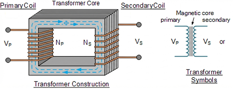
The transformer is a core component of any power system, and it works on Faraday’s Law of Induction. In low-voltage applications from 110 V to 1000 V it handles final distribution, isolation of industrial control supplies and voltage matching. Physically it is a static device that transfers energy between two or more electrically isolated circuits through a strongly coupled magnetic field 1.
When the primary winding is connected to an AC supply, the current establishes an alternating flux $\phi(t)$ in the magnetic core. By Faraday’s law the rate of change of that flux determines the electromotive force (EMF) induced in the windings. For an ideal transformer the induced voltage $E$ relates to frequency $f$, turns $N$ and peak flux $\phi_{max}$ as:
$$E = 4.44 f N \phi_{max}$$
The equation shows the basic design trade-off: at a fixed voltage, reducing size (a smaller core cross-section, and therefore a lower $\phi_{max}$) requires more turns $N$ or a higher operating frequency $f$. This is why an aircraft transformer at 400 Hz is far smaller and lighter than a 50/60 Hz unit of the same rating.
1.2 Ideal and Real Transformer Models
The ideal model assumes infinite core permeability (no magnetising current), no hysteresis or eddy-current loss, and windings with no resistance and no leakage flux. The voltage ratio is then exactly the turns ratio $a = N_1/N_2$ and input power equals output power.
In real applications below 1000 V, the non-ideal properties matter a great deal:
-
Leakage flux: not all flux produced by the primary links the secondary. Part of it closes through air, creating leakage inductance. In the equivalent circuit this appears as a series reactance $X_l$ and directly affects voltage regulation 2.
-
Saturation: the non-linearity of the B-H curve means that when the voltage is too high, magnetising current rises sharply and distorts, generating odd harmonics.
-
Core loss and copper loss: these are the decisive factors for efficiency standards such as DOE 2016 and EU Ecodesign.
2. Construction and Materials
In low-voltage dry-type transformer (LVDT) design, the choice of construction determines cooling performance, mechanical strength and electrical insulation.
2.1 Core Technology: Grain-oriented Steel and Amorphous Alloy
The core’s job is to provide a low-reluctance path.
-
Cold-rolled grain-oriented steel (CRGO): still the mainstream material. Cold rolling aligns the grains with the rolling direction, which raises permeability considerably and lowers hysteresis loss. Modern processing uses laser scribing to refine the magnetic domains further and reduce loss 3.
-
Amorphous metal: produced by melting iron, boron and silicon and then quenching so rapidly that the atoms stay disordered. Its hysteresis loss is extremely low — only 20–30% of CRGO. However, amorphous alloy is hard and brittle, sensitive to mechanical stress, and saturates at a lower flux density (about 1.56 T against 2.0 T for CRGO), so the core is physically larger. Its use in high-efficiency low-voltage transformers, particularly products meeting Tier 2, is increasing steadily 5.
2.2 Winding Technique: Foil and Wire
At 110 V–1000 V the main challenge is high current.
-
Foil winding: on the low-voltage (high-current) side, full-width copper or aluminium foil replaces wire. This removes the helix angle, so axial forces during a short circuit are almost zero and mechanical strength is greatly improved. Foil windings also have a low volts-per-layer stress, which makes the insulation more reliable 6.
-
Vacuum pressure impregnation (VPI) and cast resin:
-
VPI: a polyester or epoxy varnish is drawn into the insulation paper and windings under vacuum and then cured with heat. The process costs less and cools better, and suits standard indoor applications.
-
Cast resin: the winding is fully encapsulated in epoxy. It resists moisture, dust and short-circuit forces extremely well and suits harsh industrial environments such as chemical plants and mines, but it relies on surface convection for cooling, so its overload capability is relatively limited 7.
-
[Figure 2.1: cross-sections of a VPI dry-type transformer and a cast-resin transformer, showing the difference in insulation layers and cooling ducts.]
3. Transformer Loading
3.1 Thermal Life and Insulation Ageing
The life of a transformer is essentially the life of its insulation. IEEE C57.96 notes that the insulation life of a dry-type transformer follows the Arrhenius reaction-rate equation. For class H insulation (180 °C class, common in low-voltage transformers), the design hot-spot temperature is normally a 150 °C rise on top of a 30 °C ambient.
Running above the rated temperature accelerates depolymerisation of the insulation paper or enamel film, reducing dielectric and mechanical strength. The rule of thumb is that every 10 °C rise halves insulation life. Load management is therefore fundamentally about controlling hot-spot temperature 1.
3.2 K-factor and Non-linear Loads
Modern commercial and industrial sites are full of rectifiers, variable frequency drives (VFDs) and LED drivers, so the current contains substantial harmonic content.
-
Skin effect: high-frequency harmonic current tends to flow near the conductor surface, reducing the effective cross-section and raising AC resistance.
-
Proximity effect: the alternating field of one conductor induces eddy currents in its neighbours, adding further loss.
A standard transformer supplying non-linear loads will overheat badly. The K-factor transformer is designed for exactly this duty, with the K-factor quantifying its ability to withstand harmonic heating:
$$K = \sum I_h^2 h^2 / \sum I_h^2$$
where $h$ is the harmonic order and $I_h$ the per-unit current of that harmonic. K-4, K-13 and K-20 are common ratings. In design terms, a K-factor transformer uses finer parallel conductors (to limit the skin-depth penalty), a double-sized neutral (for additive triplen harmonics) and a lower flux density 9.
4. Multiple Winding Transformers
4.1 Construction and Applications
Most distribution transformers have two windings, but three-winding transformers are not unusual in complex industrial distribution. A 480 V input may have to supply both a 208 V power circuit and a 120 V lighting circuit — usually done with taps or separate transformers, but a multi-winding unit is used where isolation is required.
Analytically, a three-winding transformer cannot be treated as two two-winding transformers. Its equivalent circuit is a star (T) network in which the windings are coupled through mutual and leakage inductance. The short-circuit impedances are derived from the short-circuit tests between each pair of windings:
$$Z_1 = \frac{1}{2} (Z_{12} + Z_{13} – Z_{23})$$
$$Z_2 = \frac{1}{2} (Z_{12} + Z_{23} – Z_{13})$$
$$Z_3 = \frac{1}{2} (Z_{13} + Z_{23} – Z_{12})$$
These expressions are essential for calculating fault current in systems fed from more than one source 1.
5. The Autotransformer
5.1 Principle and Capacity Advantage
The autotransformer is a highly economical solution in low-voltage work, especially where the voltage ratio is close to 1 (600 V down to 480 V, for example). Primary and secondary share part of the same winding, and energy reaches the load in two ways: by electromagnetic induction and by direct conduction.
The ratio between the physical size of an autotransformer and its rated power is called the co-ratio:
$$\frac{S_{physical}}{S_{rated}} = \frac{V_{HV} – V_{LV}}{V_{HV}} = 1 – \frac{1}{a}$$
When the ratio $a$ approaches 1, the physical rating is far smaller than the throughput rating. Stepping 480 V down to 400 V ($a = 1.2$), the physical capacity is only 16.7% of the load — which means much lower volume, weight, copper loss and core loss 1.
5.2 Limitations and Risks
For all its efficiency, the autotransformer has two significant limitations between 110 V and 1000 V:
-
No galvanic isolation: an earth fault or lightning surge on the high-voltage side is conducted straight through to the low-voltage side. This rules it out for control circuits and medical locations where safety isolation is required.
-
Low short-circuit impedance: with less physical winding, the leakage reactance is very low. A secondary short circuit can draw 20–40 times rated current, against 10–20 times for a conventional transformer, so the upstream breaker needs a much higher interrupting rating (kA) 10.
[Figure 5.1: autotransformer connection diagram showing current directions in the series and common windings, and how conducted and induced power divide.]
6. The Current Transformer
6.1 Operating Principle and Saturation
The current transformer (CT) is the key metering and protection component in a low-voltage switchboard. It operates close to a short-circuited transformer: the primary current $I_1$ is set by the load on the circuit and is unaffected by the CT itself. The CT must generate enough secondary voltage to drive the connected burden so that the ampere-turn balance $I_1 N_1 \approx I_2 N_2$ is maintained 12.
The critical characteristic of a low-voltage CT is saturation.
-
Metering class: requires high accuracy near rated current (5 A, say) but should saturate early at high current — a low instrument security factor (FS) — so that the connected instruments are not damaged by fault current.
-
Protection class: must not saturate at fault currents of many times rated current (20 times, typically), so that the protection relay reads the fault waveform correctly. IEC 61869-2 uses designations such as “5P20”, meaning less than 5% error at 20 times rated current 14.
6.2 The Danger of an Open Secondary
Open-circuiting a CT secondary during maintenance below 1000 V is extremely dangerous. Once the secondary is open, the demagnetising ampere-turns disappear and the entire primary load current becomes magnetising current, driving the core deep into saturation. From $E = -N \frac{d\phi}{dt}$, the rate of change of flux at each zero crossing becomes enormous and induces peak voltages of several kilovolts in the secondary — enough to break down insulation or electrocute personnel 15.
7. Three Phase Transformers
7.1 Vector Groups and Harmonic Behaviour
In 110 V–1000 V systems the vector group of a three-phase transformer is critical to both system earthing and harmonic performance.
-
Delta-wye (Dyn1/Dyn11): the most common distribution arrangement. The delta primary lets third-harmonic current circulate inside the winding instead of flowing into the network, while the wye secondary provides a neutral for single-phase loads such as 277 V lighting. The 30-degree phase shift also helps suppress certain higher-order harmonics 16.
-
Wye-wye (Yyn0): simple, but without a delta tertiary the third harmonic causes the neutral potential to float and phase voltages to become unbalanced. It is normally used only with three-limb cores — where the reluctance of the core structure itself suppresses zero-sequence flux — or with a delta stabilising winding.
-
Zigzag (Zn): splitting each phase winding across two limbs forces the three phase currents into balance. Widely used in grounding transformers to give a delta system an artificial neutral, and excellent at filtering zero-sequence harmonics 1.
7.2 The Effect of Core Construction
The magnetic circuit of a three-phase transformer — three-limb or five-limb — determines its zero-sequence impedance.
-
Three-limb: the three phase fluxes sum to zero. Under unbalanced load, however, zero-sequence flux has to return through the tank or the air, where reluctance is very high; zero-sequence impedance is therefore low, but the tank may overheat.
-
Five-limb: the side yokes give zero-sequence flux a low-reluctance path, so zero-sequence impedance is high (close to the magnetising impedance) and the magnetic circuit is more linear 1.
8. The Per-unit System
8.1 Definition and Calculation
A per-unit (pu) value normalises a physical quantity against a base value. For transformers it removes the difference in voltage level, so primary and secondary impedances can be compared directly.
$$Z_{pu} = \frac{Z_{actual} (\Omega)}{Z_{base} (\Omega)}$$
where the base impedance is $Z_{base} = \frac{V_{base}^2}{S_{base}}$.
8.2 A Low-voltage Worked Example
Take a 1000 kVA, 480 V transformer with 5% impedance (0.05 pu).
-
Base impedance:
$$Z_{base} = \frac{480^2}{1000 \times 1000} = 0.2304 \, \Omega$$
-
Actual short-circuit impedance in ohms:
$$Z_{actual} = 0.05 \times 0.2304 = 0.01152 \, \Omega$$
-
Short-circuit current:
$$I_{sc, pu} = \frac{V_{pu}}{Z_{pu}} = \frac{1.0}{0.05} = 20 \, \text{pu}$$
That is, 20 times rated current. Working in per-unit lets an engineer size the breaker immediately, without converting back and forth between voltage levels 17.
9. Transformer Voltage Regulation
9.1 Definition and Phasor Analysis
Voltage regulation (VR) measures how well a transformer holds its output voltage.
$$\%VR = \frac{V_{no-load} – V_{full-load}}{V_{full-load}} \times 100\%$$
assuming constant primary voltage 2.
In a low-voltage system the cable impedance acts together with the transformer impedance. The internal impedance $Z_{eq} = R_{eq} + jX_{eq}$ produces a drop under load current.
9.2 The Decisive Role of Power Factor
Voltage regulation depends heavily on the load power factor:
-
Lagging PF (inductive): current lags voltage. The impedance drop is nearly in line with the terminal voltage, so the voltage falls noticeably. This is the usual case.
-
Unity PF (resistive): the drop is dominated by the resistive component; the reactive component contributes less because it is at right angles to the terminal voltage.
-
Leading PF (capacitive): current leads voltage. The reactive drop reverses and can compensate the fall, so full-load voltage may even exceed no-load voltage — negative regulation, the local equivalent of the Ferranti effect 19.
An approximation suitable for low-voltage transformers:
$$\%VR \approx (R_{pu} \cos \phi + X_{pu} \sin \phi) \times 100$$
This shows that in a typical low-voltage dry-type transformer, where the $X/R$ ratio is low (roughly 1–3), the resistive component $R$ contributes far too much to voltage regulation to be ignored 19.
[Figure 9.1: transformer phasor diagrams at different power factors, showing how the $I \cdot Z$ drop affects the magnitude of $V_2$.]
10. Losses in Real Transformers and International Efficiency Standards
As energy efficiency has risen up the agenda worldwide, efficiency standards for low-voltage transformers — distribution transformers above all — have become decisive in both design and procurement.
10.1 Types of Losses
10.1.1 No-load Losses (Core Losses)
A fixed loss present whenever the transformer is energised, independent of load.
-
Mechanism: hysteresis loss (from domain friction, proportional to frequency) and eddy-current loss (from currents induced in the core, proportional to the square of frequency and the square of lamination thickness).
-
What affects it: core material (M3, M4, Hi-B steel or amorphous alloy), lamination technique and operating voltage. Because low-voltage transformers are usually energised 24 hours a day, reducing no-load loss is the key to saving energy — the A factor in a TOC evaluation is normally high 21.
10.1.2 Load Losses (Conductor Losses)
Losses that vary with load current, proportional to its square ($P \propto I^2$).
-
DC resistance loss ($I^2R$): ohmic heating in the conductors themselves.
-
Eddy losses in conductors: eddy currents induced inside the conductors by leakage flux. In low-voltage, high-current windings such as foil windings, poor design can make this loss substantial 22.
10.1.3 Stray Losses
Eddy-current losses induced by leakage flux in metallic structural parts — clamps, enclosure, bolts. In high-current transformers below 1000 V, stray loss can create local hot spots, which are controlled with magnetic shunts or non-magnetic materials 1.
10.2 Efficiency Metrics
Full-load efficiency is no longer the only figure that matters. Modern standards look at efficiency at a defined load factor (35% or 50%), which reflects how distribution transformers actually run.
-
Peak Efficiency Index (PEI): introduced by IEC 60076-20, the highest efficiency the transformer can reach.
-
Total ownership cost (TOC): $TOC = \text{Initial Cost} + A \times P_{No-Load} + B \times P_{Load}$, where A and B are the capitalised values of loss ($/watt) set by the user from the electricity tariff and expected life.
10.3 International Efficiency Standards
Most countries now apply mandatory minimum energy performance standards (MEPS) to low-voltage transformers, dry-type units in particular. The main regional requirements are:
| Region | Standard | Scope (low voltage) | Key metric | Notes |
|---|---|---|---|---|
| Europe | Ecodesign Regulation (EU) 2019/1783 | >1 kVA | Maximum loss (W) | Tier 2 mandatory since July 2021. Rather than specifying an efficiency percentage, it caps no-load ($P_0$) and load ($P_k$) losses in watts. Industrial transformers below 1.1 kV are covered explicitly 24. |
| United States | DOE 2016 (10 CFR 431) | 15–2500 kVA (dry) | Minimum efficiency % | Measured at 35% load and a 75 °C reference temperature. A large step up from TP-1, it pushed the industry towards higher-permeability materials 26. |
| Canada | CSA C802.2-18 / NRCan 2019 | 15–7500 kVA | Minimum efficiency % | Closely harmonised with DOE 2016. Sets the minimum efficiency of dry-type transformers at 35% load, replacing the older C802.2-12 28. |
| Australia / New Zealand | AS 2374.1.2 / AS/NZS 60076 | 10–2500 kVA | Minimum efficiency % | Measured at 50% load, unlike the North American 35%. A High Efficiency Performance Level (HEPL) exists as a voluntary premium tier 30. |
| India | IS 1180 (Part 1): 2014 | up to 2500 kVA | Maximum loss (W) | Operates a star rating (1 to 5 stars); Level 2 (1 star) is normally mandatory. Applies below 33 kV and covers distribution transformers with a 415 V secondary 32. |
| Brazil | ABNT NBR 5356 / 5440 | — | Efficiency / loss | Follows the IEC standards, with separate loss limits for liquid-immersed and dry-type transformers. A 2013 ministerial decree tightened the MEPS further 30. |
10.3.1 IEC 60076 and Ecodesign (Europe)
The EU Ecodesign Directive takes an aggressive line. Tier 2, in force since 2021, demands very low no-load loss; for a 1000 kVA transformer the permitted no-load loss is pushed down hard. Manufacturers have had to move to high-grade grain-oriented steel or amorphous alloy and to optimise core design so that processing stress does not add loss 35. Note that the regulation exempts certain special-purpose transformers (instrument transformers, welding transformers), but covers general-purpose low-voltage distribution transformers comprehensively 25.
10.3.2 DOE 2016 (United States)
The US Department of Energy standard targets low-voltage dry-type transformers (LVDT) specifically. Its efficiency curve peaks at 35% load, reflecting the low average loading of transformers in US commercial buildings. The standard pushed the market from conventional electrical steel towards thinner, more highly grain-oriented material, and to amorphous alloy in some high-efficiency models 36.
10.3.3 Other Regions
-
Canada (CSA): the NRCan 2019 regulation references CSA C802.2-18 directly, and its efficiency values match DOE 2016, removing a trade barrier within North America. For dry-type transformers at or below 1.2 kV this means efficiency has to be designed in from the start 28.
-
India (BIS): IS 1180 is unusual in specifying losses not only at full load but strictly at 50% load as well, which suits the heavily varying loads on the Indian grid. The star labelling scheme also lets non-technical buyers identify efficient products easily 32.
11. Selecting a High-efficiency Transformer
Match the transformer to the load profile:
-
Lightly loaded sites (office buildings, standby supplies): choose a transformer with low no-load (core) loss, such as an amorphous-core unit, because the transformer spends most of its time lightly loaded and core loss dominates total loss. DOE 2016 products perform best in this role.
-
Heavily loaded sites (industrial motors, data centres): choose low load (copper) loss — usually larger conductor cross-sections, and often all-copper windings — because $I^2R$ loss dominates. The strict full-load loss limits of European Tier 2 suit this duty 21.
12. Case Study
Energy retrofit in a commercial building
A mixed-use commercial complex replaced its ageing TP-1 dry-type transformers (480 V/208 V) with high-efficiency units meeting DOE 2016.
-
Background: the old transformers averaged only 20% load, yet their core loss produced heat continuously and added to the air-conditioning load.
-
The retrofit: new transformers with optimised core design cut no-load loss by 40%.
-
Result: besides the direct electricity saving, less heat in the electrical room significantly reduced cooling demand. The TOC analysis showed a payback of about 3.5 years — shorter still once the air-conditioning saving is counted 38.
13. Conclusion
In the 110 V–1000 V range, the transformer has moved from being a simple voltage-changing device to a control point for system energy efficiency. Whether the answer is amorphous alloy to meet Tier 2 or DOE 2016, or a K-factor design to cope with harmonics, engineers need to work from total ownership cost, combining the actual load profile with the regulations that apply locally, to arrive at the optimal design and selection.