Open Delta (V-V) Connections and the 190 V High Leg: Utilisation Factors Explained
Is the utilisation of a V-V connection 0.577 or 0.866? Both — measured against different bases. This report derives each factor, explains the internal 30° displacement, and shows why the high leg of a 110 V/220 V combined service measures 190 V.
14 min read

In this article
Abstract
This report analyses two unusual transformer connections found in distribution systems: the V-V (open delta) connection and the “lighting and power combined service” system derived from it. Two questions that have long caused confusion in practice are worked through mathematically and physically. The first is the capacity utilisation of a V-V connection — is it 0.577 (57.7%) or 0.866 (86.6%)? The report establishes the base each figure is measured against and where each applies. The second is why the high-leg-to-ground voltage measures 190 V in the 110 V/220 V combined-service systems common in Taiwan and in some US-derived networks.
Using vector analysis, complex power calculation and geometric derivation, the report shows that the 0.577 figure is the capacity ratio relative to the original complete three-phase bank, while 0.866 is the internal power-factor limit on the equipment actually installed. Simple triangle geometry then proves that 190 V is a geometric inevitability of a centre-tapped delta system, exactly $\sqrt{3}$ times the single-phase voltage. The report also covers how these systems behave under load imbalance and harmonics, and what the safety codes (NEC and the Taiwanese wiring regulations) require — a reference with both theoretical depth and practical value for power engineers.
Chapter 1. Introduction
1.1 Background
Throughout the development of distribution networks, one core design challenge has persisted: how to serve an industrial customer’s three-phase power needs (induction motors, compressors) and a commercial or residential customer’s single-phase lighting and appliance needs at the same time. The standard three-phase four-wire wye system (380Y/220 V or 208Y/120 V) dominates new work today, but delta systems still make up a large share of the installed base.
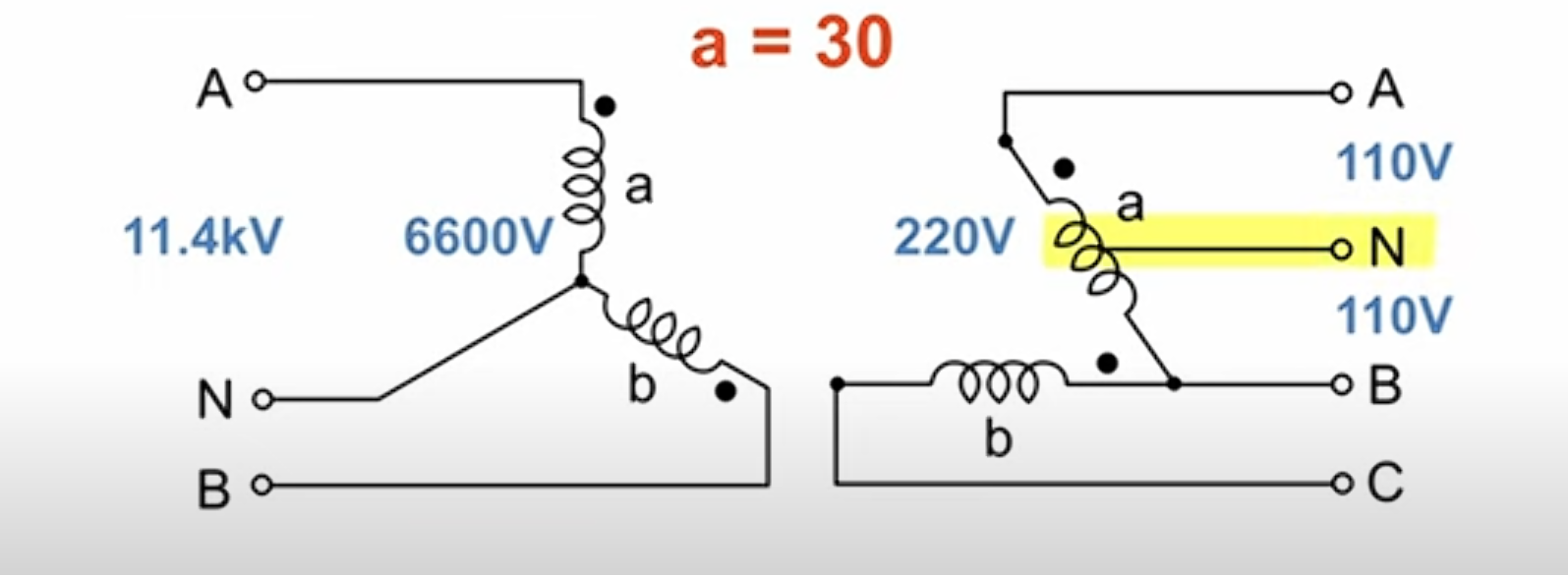
In Taiwan and North America in particular, several special transformer connections were developed to serve mixed loads from limited transformer capacity. The V-V or open delta connection supplies three-phase power from only two single-phase transformers, which makes it useful for emergency restoration and for lightly loaded three-phase supplies. To obtain a single-phase neutral from a delta system as well, the high-leg delta — the “lighting and power combined service” — evolved from it.
These asymmetric systems bring economic and operational benefits, but they also introduce complicated voltage vector relationships and capacity derating. Engineers frequently ask why the combined rating of two transformers cannot be fully used, and why a non-standard 190 V appears in the system. Without clear theory behind the answers, it is easy to specify the wrong equipment or create a safety hazard.
1.2 Scope
The report addresses two central technical questions in full:
-
The V-V utilisation puzzle: the physical meaning of the 0.577 and 0.866 factors, how each is derived, and where each applies.
-
The geometry behind 190 V: a mathematical model of the high-leg-to-ground voltage in a 110 V/220 V system, and the hazard it presents to connected equipment.
The scope covers electromagnetic analysis inside the transformer, phasor diagrams, load imbalance calculations and the relevant safety codes (the NEC and the Taipower service rules).
Chapter 2. Theory and Utilisation of the V-V (Open Delta) Connection
The V-V or open delta connection is one of the most distinctive arrangements in three-phase transformer banks. It is both the degraded operating mode of a delta-delta bank after a failure and a deliberately chosen economical supply scheme. Understanding its utilisation requires starting from the closed delta system and working through to the boundary conditions of the V-V system.
2.1 Base Case: the Closed Delta-Delta Bank
A balanced closed delta-delta bank consists of three single-phase transformers of identical rating, ratio and impedance.
-
Line voltage $V_L$ equals the winding (phase) voltage $V_{ph}$:
$$V_{L} = V_{ph}$$
-
Line current $I_L$ is $\sqrt{3}$ times the phase current, by Kirchhoff’s current law at each vertex:
$$I_{L} = \sqrt{3} \times I_{ph}$$
-
Total capacity $S_{\Delta}$ is the sum of the three transformers:
$$S_{\Delta} = 3 \times V_{ph} \times I_{ph} = \sqrt{3} \times V_{L} \times I_{L}$$
This is the base case for everything that follows.
2.2 How a V-V Connection Forms, and How the Current Paths Change
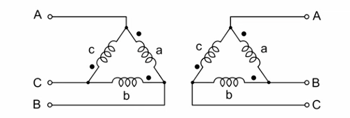
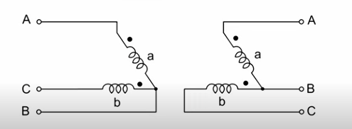
When one transformer in a delta-delta bank (say the C-phase unit) is removed or disconnected after a fault, the remaining two units (A and B) form a V-V connection 1.
The electrical topology then changes fundamentally:
-
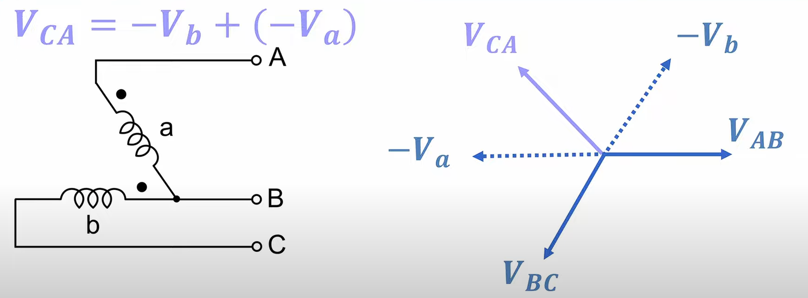
Voltages are maintained: even with one transformer missing, vector addition means the negative sum of the two remaining voltage vectors $V_{AB}$ and $V_{BC}$ still synthesises the third line voltage $V_{CA}$. Geometrically, the three line voltages stay balanced, ignoring the voltage drop caused by load.
-
Current paths change: this is the key to the derating. In a closed delta the line current $I_L$ divides between two windings; in a V-V connection the line current flows directly through the transformer winding.
$$I_{ph(V-V)} = I_{L(V-V)}$$
To keep the windings from overheating, the maximum permissible line current of a V-V system is therefore limited to the rated phase current of a single transformer ($I_{rated}$).
2.3 The Two Utilisation Factors: 0.577 and 0.866
To the central question — is the utilisation 0.577 or 0.866? — the answer is that both are correct, but they are measured against different bases. There is no contradiction: one is the system view, the other the component view.
The table below summarises the definitions:
| Factor | Expression | Value | Physical meaning | Where it is used |
|---|---|---|---|---|
| System capacity ratio | $\frac{S_{V-V}}{S_{\Delta(\text{Original})}} = \frac{1}{\sqrt{3}}$ | 0.577 (57.7%) | The output capability of the V-V system relative to the original complete three-transformer bank. | Fault analysis: when one transformer fails, how much of the original load can the remaining bank still carry? |
| Transformer utility factor | $\frac{S_{V-V}}{S_{\text{Installed}}} = \frac{\sqrt{3}}{2}$ | 0.866 (86.6%) | The output of the V-V system relative to the combined nameplate rating of the two transformers actually installed. | New designs: when V-V is chosen deliberately, how efficiently is the equipment investment used? |
2.3.1 Derivation: 0.577 (System Capacity Ratio)
Let the rating of one transformer be $S_1$.
-
Original closed delta capacity: $S_{closed} = 3 \times S_1$.
-
V-V capacity:
Because $V_L = V_{ph}$ and $I_L = I_{ph(rated)}$, the three-phase power is:
$$S_{open} = \sqrt{3} \times V_L \times I_L = \sqrt{3} \times V_{ph} \times I_{ph(rated)} = \sqrt{3} \times S_1$$
-
The ratio:
$$\text{Ratio} = \frac{S_{open}}{S_{closed}} = \frac{\sqrt{3} \times S_1}{3 \times S_1} = \frac{\sqrt{3}}{3} = \frac{1}{\sqrt{3}} \approx 0.577$$
Conclusion: losing one transformer from a three-phase bank does not simply remove a third of the capacity (leaving 66.7%); capacity falls all the way to 57.7% 1. The additional 9% loss (66.7% − 57.7%) comes from the phase constraint created by the changed current path.
2.3.2 Derivation: 0.866 (Transformer Utility Factor)
Now suppose two transformers of rating $S_1$ are installed.
-
Installed capacity: $S_{installed} = 2 \times S_1$.
-
Deliverable three-phase capacity: $S_{open} = \sqrt{3} \times S_1$, as derived above.
-
The ratio:
$$\text{Utility Factor} = \frac{S_{open}}{S_{installed}} = \frac{\sqrt{3} \times S_1}{2 \times S_1} = \frac{\sqrt{3}}{2} \approx 0.866$$
Conclusion: in a V-V connection each transformer can only deliver 86.6% of its nameplate rating 2. Two 100 kVA transformers (200 kVA installed) can therefore supply no more than 173.2 kVA of three-phase load.
2.4 The Physics: Internal Power Factor and the $30^\circ$ Displacement
Why can the transformers not deliver 100%? Because in a V-V connection there is an inherent phase displacement between the winding voltage and the current flowing through that winding, even when the load itself has unity power factor.
2.4.1 Vector Analysis
Assume a purely resistive three-phase load at unity power factor, so that the line currents $I_A, I_B, I_C$ are $120^\circ$ apart and in phase with their respective phase voltages.
In a V-V connection, however:
-
Transformer 1 (connected across A-B) sees voltage $V_{AB}$, but the current through it is the line current $I_A$.
In the three-phase phasor diagram, $I_A$ lags $V_{AB}$ by exactly $30^\circ$.
-
Transformer 2 (connected across C-B) sees voltage $V_{CB}$, with line current $I_C$ flowing through it.
In the phasor diagram, $I_C$ leads $V_{CB}$ by exactly $30^\circ$.
2.4.2 Power Calculation
Even with a purely resistive external load (PF = 1), each transformer internally “sees” a load with a power factor of 0.866:
-
$P_{Unit 1} = V \times I \times \cos(30^\circ) = S_1 \times 0.866$
-
$P_{Unit 2} = V \times I \times \cos(-30^\circ) = S_1 \times 0.866$
This $30^\circ$ internal displacement circulates reactive power between the two transformers. Although that power never reaches the load, the apparent power (kVA) still consumes the thermal capacity of the transformers 5. That is the physical basis of the 0.866 utility factor.
Going further: the effect of load power factor
If the external load itself has a phase angle $\phi$ (an inductive load, for example):
-
Transformer 1 operates at a power-factor angle of $(30^\circ + \phi)$.
-
Transformer 2 operates at $(30^\circ – \phi)$.
When the load power factor falls to 0.5 ($\phi = 60^\circ$):
-
Transformer 1: PF $= \cos(30+60) = \cos(90^\circ) = 0$. It supplies only reactive power and no real power at all.
-
Transformer 2: PF $= \cos(30-60) = \cos(-30^\circ) = 0.866$. It carries the entire real-power output.
This extreme imbalance further restricts the use of V-V connections with low-power-factor loads, and is the main reason for the heavy derating applied in design 7.
Chapter 3. Combined Lighting and Power Service, and the Geometry of 190 V
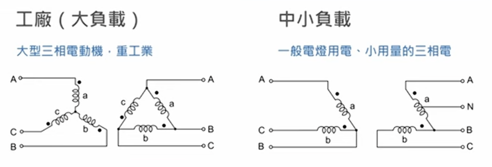
The other great challenge in distribution is deriving a single-phase supply from a three-phase system. In North America and Taiwan the usual solution is to centre-tap one delta winding and earth it, producing the four-wire delta, also called the high-leg (or “red leg”) delta.
3.1 System Topology: Combined 110 V/220 V Service
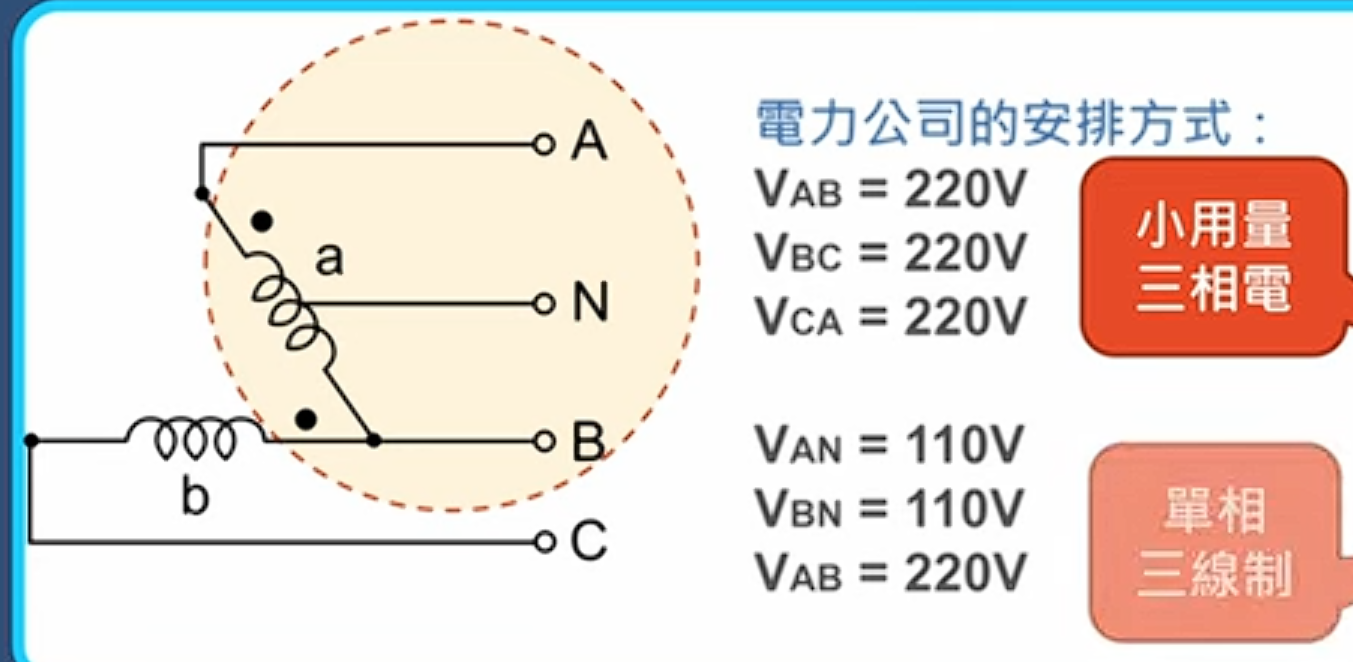
In such a system — common in general factories and mixed commercial/residential buildings in Taiwan:
-
Lighting pot: one side of the delta triangle (the A-C side, say), normally the larger winding. Its midpoint is earthed and becomes the neutral (N).
-
$V_{AN} = 110V$
-
$V_{CN} = 110V$
-
$V_{AC} = 220V$
-
This part forms a standard single-phase three-wire 110/220 V system for lighting and socket outlets.
-
Power pot: the other two sides of the delta (or the other side of a V-V bank), providing the voltages needed to synthesise three-phase supply.
-
$V_{AB} = 220V$
-
$V_{BC} = 220V$
-
-
High leg (B phase): the vertex of the delta triangle opposite the earthed midpoint.
3.2 Deriving the 190 V
Why does a 190 V appear at all?
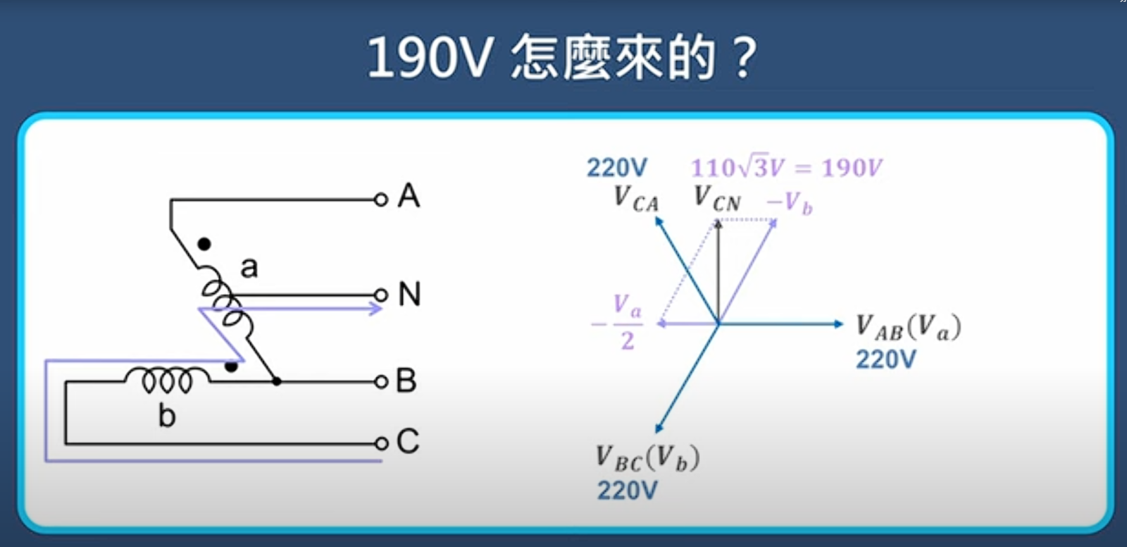
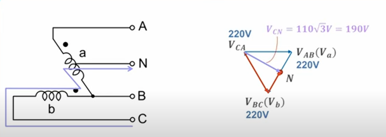
The figure is not arbitrary — it follows strictly from Euclidean geometry and trigonometry. It is the potential difference measured from the B-phase conductor to the earthed neutral (N).
3.2.1 The Geometric Model
Draw the voltage vectors on the complex plane:
-
Let side A-C be the base, its length the line voltage $V_{LL} = 220V$.
-
Neutral N sits exactly at the midpoint of A-C, so vectors $AN$ and $NC$ are each $110V$.
-
Vertex B forms an equilateral triangle with A and C, because the system is balanced and every line voltage is 220 V.
The goal is the distance from vertex B to midpoint N — the magnitude $|V_{BN}|$.
3.2.2 The Calculation
In equilateral triangle ABC, BN is the altitude onto base AC.
By Pythagoras, in the right triangle ANB:
-
Hypotenuse $AB = 220V$
-
Base $AN = 110V$
-
Altitude $BN = V_{High-Leg}$
$$V_{BN}^2 + V_{AN}^2 = V_{AB}^2 \\ V_{BN}^2 + 110^2 = 220^2 \\ V_{BN} = \sqrt{220^2 – 110^2} \\ V_{BN} = \sqrt{48400 – 12100} = \sqrt{36300} \\ V_{BN} \approx 190.525 V$$
Or directly by trigonometry:
$$V_{BN} = V_{AB} \times \sin(60^{\circ}) = 220 \times \frac{\sqrt{3}}{2} = 110 \times \sqrt{3}$$
Since $\sqrt{3} \approx 1.732$:
$$V_{BN} \approx 110 \times 1.732 = 190.52V$$
Conclusion: in a 110 V/220 V system the high-leg-to-ground voltage is exactly $110\sqrt{3}$, or about 190 V. That is where the figure comes from 9.
3.3 Comparison with the US 120 V/240 V System
Much of the engineering literature — NEC-based US references especially — refers to a “208 V high leg”. That is simply because the standard single-phase voltage in the US is 120 V rather than Taiwan’s 110 V.
| System | Base single-phase voltage ($V_{AN}$) | Line voltage ($V_{LL}$) | High-leg calculation | High-leg voltage ($V_{BN}$) |
|---|---|---|---|---|
| Taiwan / Japan | 110 V | 220 V | $$110 \times \sqrt{3}$$ | ~190 V |
| United States | 120 V | 240 V | $$120 \times \sqrt{3}$$ | ~208 V |
The table makes it clear that 190 V and 208 V differ only in the base voltage; the geometry behind them is identical. Keep the distinction in mind when reading technical material from other countries.
3.4 The Hazard of the High Leg, and Identifying It (the Orange Leg)
The presence of that 190 V is a serious safety issue.
-
Risk of mis-connection: if someone treats the B phase (high leg) as an ordinary live conductor and pairs it with the neutral to supply a 110 V appliance — a computer, a light, a charger — the appliance is subjected to 190 V.
-
The electrical consequence follows from:
-
$\text{Power} = \frac{V^{2}}{R}$
Raising the voltage from 110 V to 190 V (about 1.73 times) raises the power by $1.73^2 \approx 3$ times. Resistive loads such as lamps fail instantly, and the varistors in electronic equipment can rupture 12.
Code requirements
To prevent such accidents, NEC Articles 110.15 and 230.56, and the Taiwanese interior wiring regulations, both require:
-
Colour identification: the high-leg conductor must be marked in orange, which is why it is commonly called the “orange leg” (or “red leg” in Taiwan).
-
Position in the board: the B phase (the centre position) is designated as the high leg, and single-pole breakers should not be installed on it unless they are rated for 220 V insulation and serve a 220 V load 9.
Chapter 4. Design and Operating Considerations for Combined Service
Combining a V-V connection with combined lighting and power service — the open-delta high-leg system — is a very common arrangement, particularly where the loads are asymmetric. This chapter covers the key design parameters in practice.
4.1 Asymmetric Transformer Sizing
In this system the two transformers do not share load equally.
-
Main (lighting) pot: carries 100% of the single-phase lighting load ($S_{1\phi}$) plus part of the three-phase load ($S_{3\phi}$).
-
Teaser (power pot / kicker): carries only part of the three-phase load.
Rule-of-thumb sizing 15
For accurate selection, use:
-
Lighting transformer capacity ($kVA_{Main}$):
$$kVA_{Main} = S_{1\phi} + \frac{S_{3\phi}}{\sqrt{3}} \approx S_{1\phi} + 0.58 \times S_{3\phi}$$
-
Power transformer capacity ($kVA_{Teaser}$):
$$kVA_{Teaser} = \frac{S_{3\phi}}{\sqrt{3}} \approx 0.58 \times S_{3\phi}$$
Worked example
A factory has 30 kVA of single-phase load (110 V lighting and outlets) and 50 kVA of three-phase motor load.
-
$kVA_{Teaser} = 0.58 \times 50 = 29\ kVA$ → select the standard 37.5 kVA unit.
-
$kVA_{Main} = 30 + 29 = 59\ kVA$ → select the standard 75 kVA unit.
This “one large, one small” pairing is characteristic of open-delta systems and saves equipment cost — provided the calculation is done carefully, because the smaller transformer overloads easily.
4.2 Voltage Imbalance and Neutral Shift
One inherent weakness of the V-V connection is poor voltage regulation.
-
In a closed delta, each phase voltage is clamped by a real winding.
-
In a V-V system the voltage across the open side ($V_{CA}$) is synthesised from the other two phases. As load increases, the internal impedance drop makes that synthesised voltage collapse or shift in phase.
Drift of the high-leg voltage
In a combined-service system, if the 110 V loads on the A-N and C-N sides are badly unbalanced (A fully loaded, C unloaded, say), the potential of neutral N shifts. Because the 190 V high leg is measured relative to N, that shift translates directly into fluctuation of the high-leg-to-ground voltage. The fluctuation can disturb voltage-sensitive three-phase equipment and even trigger the input phase-loss or overvoltage protection of a variable frequency drive 3.
4.3 Harmonics and Zero-sequence Current
In a standard delta system, triplen harmonics circulate inside the triangle and never reach the source. In a V-V connection the triangle is open, so the harmonic current has no closed loop to circulate in and flows out into the lines instead, distorting the waveform on the supply side. In a modern facility with many non-linear loads — computers, LED drivers — this can create power-quality problems that require an additional filter.
Chapter 5. Conclusions and Recommendations
From the derivations and practical analysis above, the two questions can be answered as follows.
5.1 Summary
-
On V-V utilisation:
-
0.577 (57.7%) is the system capacity ratio: after one of three transformers fails, the bank can supply 57.7% of its original capacity. This is the figure to use when assessing recovery from a fault.
-
0.866 (86.6%) is the component utility factor: in a V-V arrangement the internal $30^\circ$ displacement means each transformer can deliver only 86.6% of its nameplate rating. This is the derating figure to use when specifying equipment for a new system.
-
The two are mathematically consistent ($\frac{1}{\sqrt{3}}$ against $\frac{\sqrt{3}}{2}$); they differ only in whether the denominator is the rating of three transformers or of two.
-
-
On the 190 V:
-
It is the geometric inevitability of a centre-tapped delta transformer in a 110 V/220 V system.
-
Its value is $110V \times \sqrt{3} \approx 190.5V$ — the vector altitude from the earthed neutral to vertex B.
-
It is destructive to 110 V equipment, so the orange identification and B-phase placement rules must be followed strictly.
-
5.2 Recommendations for Practice
-
Marking and management: in existing combined-service installations, facility managers should audit every distribution board to confirm the high leg (B phase) is clearly marked in orange, and prohibit general single-phase outlet circuits from being connected to it.
-
Equipment selection: always apply the $0.866$ derating factor when sizing transformers for an open-delta supply. Where there is substantial single-phase load, use the asymmetric sizing formulas ($S_{Main} > S_{Teaser}$).
-
Modernisation: given the inherent weaknesses of V-V systems in voltage balance and harmonic behaviour, new or fully refurbished plants should prefer a three-phase four-wire wye system (208Y/120 V or 380Y/220 V) for better power quality and safety.
The V-V connection and the high-leg delta are products of real engineering ingenuity that solved the economic and technical constraints of their time. In today’s environment of precision loads, however, their operating characteristics need to be understood and managed with considerably more care.
A note on references: this report draws on a range of technical literature and standards, with superscripts marking the source of data and theory. The citations include TutorialsPoint 1, Electrical PE Review 17, NEC code commentary 9 and various power engineering forum discussions 13.