
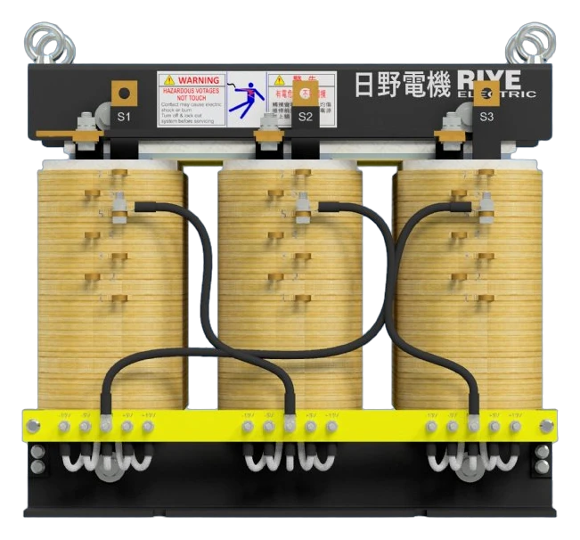
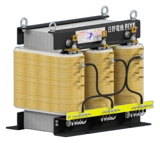
Dry type Transformer
K Factor Transformer Series
Model: K Factor Transformer
Purpose-engineered to handle harmonic currents generated by non-linear loads.
- Capacity up to 1000 kVA
- Rating K-4 to K-20
- Voltage 208V–480V
- Efficiency > 99%
Specifications
| Item | Value |
|---|---|
| Product Type | Low-Voltage Dry-Type K-Factor Isolation Transformer |
| Rated Capacity | Up to 1000 kVA (Three-Phase) |
| Primary Voltage | 480V Delta, 208V Delta (Custom voltages available) |
| Secondary Voltage | 208Y/120V, 480Y/277V (3-Phase, 4-Wire Wye) |
| Rated Frequency | 60 Hz (50 Hz optional) |
| K-Factor Ratings | K-4, K-9, K-13, K-20 |
| Neutral Rating | 200% Continuous Phase Current Rated Busbar |
| Winding Material | High-Conductivity Copper (Optional Electrical Aluminum) |
| Insulation Class | Class H |
| Temperature Rise | 150°C (Optional 115°C or 80°C low temperature rise) |
| Full Capacity Taps | 2 @ +2.5% FCAN, 4 @ -2.5% FCBN (6 total tap positions) |
| Electrostatic Shield | Interleaved Copper Shield (Attenuation > 60 dB) |
| Efficiency Standard | US DOE 2016 Compliant (10 CFR Part 431 Subpart K) |
| Cooling Type | Natural Convection Air-Cooled (AA / ANN) |
| Enclosure Rating | NEMA 1 / IP20 (Indoor; optional NEMA 3R outdoor) |
| Design Standards | UL 1561, ANSI/IEEE C57.110, NEMA ST-20, NFPA 70 (NEC) |
Overview
The K-Factor Isolation Transformer is purpose-engineered to handle harmonic currents generated by non-linear loads across modern power distribution networks. With the rapid expansion of IT servers, uninterruptible power supplies (UPS), switch-mode power supplies (SMPS), variable frequency drives (VFD), and electric vehicle (EV) charging infrastructure in commercial and industrial facilities, harmonic currents induce excessive winding heating, elevated eddy current losses, and premature insulation breakdown in conventional transformers.
Designed for harsh, harmonic-rich electrical environments, this product line offers flexible voltage configurations between 208V and 480V and delivers power capacities up to 1000 kVA. Fully compliant with US Department of Energy (DOE 2016) efficiency standards, our K-Factor transformers serve as the rugged power backbone for data centers, semiconductor fabrication plants, healthcare facilities, and mission-critical installations.
Harmonic Challenges and Technical Principles
Thermal Effects of Harmonics on Transformers
Standard distribution transformers are designed for pure 60 Hz (or 50 Hz) sinusoidal currents. Non-linear loads induce harmonic currents that drastically increase transformer losses through three distinct mechanisms:
- Conductor Resistance Losses (I²R losses): Increase in direct proportion to the square of the total true RMS current.
- Winding Eddy Current Losses (P_EC): Increase proportionally to the square of the harmonic order (P_EC is proportional to h²). For instance, the eddy current loss produced by a 5th harmonic current is 25 times greater than that produced by an equal fundamental frequency current.
- Triplen Harmonic Accumulation: Odd multiples of the 3rd harmonic (3rd, 9th, 15th) are zero-sequence currents that add arithmetically in the neutral conductor of three-phase, four-wire systems. This can cause neutral current to significantly exceed full-load phase current, creating extreme overheating and fire risks in the neutral busbar.
K-Factor Technical Definition
Per ANSI/IEEE C57.110 and UL 1561, K-Factor is a weighted index quantifying a transformer’s capability to withstand harmonic thermal stress without exceeding its insulation temperature rating:
K-Factor = Σ [ (Ih / Irms)² × h² ]
A linear sinusoidal load yields K = 1; typical commercial office equipment loaded with SMPS operates at K = 4 to 9; heavy industrial VFD systems or high-density AI data centers operate at K = 13 to 20.
Core Engineering and Design Features
Optimized Core Flux Density and Advanced Winding Architecture
- Minimized Core Losses: Utilizing high-permeability, ultra-thin cold-rolled grain-oriented (CRGO) electrical steel, operating at lower flux density levels to prevent saturation, core overheating, and stray load losses caused by high-frequency harmonic flux.
- Mitigated Skin and Proximity Effects: Employing transposed conductors and specialized foil/flat-wire windings to minimize the increase in AC resistance from high-frequency skin and proximity effects while ensuring uniform heat distribution.
200% Rated Neutral Busbar
In full compliance with UL 1561, the neutral busbar is sized to 200% of the rated secondary phase current capacity to safely carry excessive triplen harmonic currents.
Example: For a 75 kVA transformer with a 208Y/120V three-phase secondary, the full-load line current is approximately 208 A. Our 200% neutral busbar is rated for at least 416 A continuous current, completely preventing thermal damage.
Electrostatic Shielding
A precision grounded copper electrostatic shield positioned between the primary and secondary windings provides over 60 dB of common-mode electrical noise attenuation, shielding sensitive downstream microelectronics and servers from utility transients and spikes.
Enhanced Thermal Management (Zero Derating Required)
While standard transformers must be de-rated to 50%–70% of capacity under non-linear loads, our units are engineered with optimized natural-convection ventilation ducts and robust thermal paths, delivering 100% full-load capacity at their rated K-Factor without exceeding allowable temperature rise limits.
Wide Voltage Capability and 1000 kVA High-Capacity Range
208V to 480V Flexible Voltage Configurations
Compatible with standard North American and global low-voltage distribution topologies:
- 480V Delta to 208Y/120V: The core configuration for North American commercial buildings and data center power distribution units (PDUs), converting 480V distribution down to 120V/208V for IT and branch circuits. The primary Delta winding traps triplen harmonics and keeps them off the upstream grid.
- 208V Delta to 480Y/277V: Step-up configuration supplying 480V motor loads or 277V lighting panels.
- 480V Delta to 480Y/277V: Isolation configuration establishing a Separately Derived System (SDS) to eliminate ground loops and common-mode noise.
- Standard Full-Capacity Taps: Equipped with 2 @ +2.5% FCAN, 4 @ -2.5% FCBN taps (6 total tap positions) to easily compensate for line impedance and field voltage variations.
Heavy-Duty Capacity up to 1000 kVA
- Conductor Material: Standard high-conductivity copper windings (high-grade electrical aluminum optional).
- Insulation System: Class H insulation system with optional 150°C, 115°C, or 80°C low temperature rise designs for extended service life and enhanced overload margin.
- Premium Energy Efficiency: Fully compliant with US DOE 2016 standards (10 CFR Part 431 Subpart K), achieving a minimum efficiency of 99.28% at 35% load for 1000 kVA three-phase low-voltage dry-type units.
Compliance and Industry Standards
Engineered, manufactured, and tested in accordance with top-tier international standards:
- UL 1561: Standard for Dry-Type General Purpose and Power Transformers (K-4, K-9, K-13, K-20 Listed)
- ANSI/IEEE C57.110: Recommended Practice for Establishing Liquid-Filled and Dry-Type Power and Distribution Transformer Capability When Supplying Nonsinusoidal Load Currents
- NEMA ST-20: Dry-Type Transformers for General Applications
- DOE 2016 (10 CFR Part 431 Subpart K): Energy Conservation Standards for Distribution Transformers
- NFPA 70: National Electrical Code (NEC Articles 450 and 250 for Separately Derived Systems)
Key Target Applications
- AI Compute Clusters and High-Density Data Centers: High-density server SMPS power supplies, extensive high-frequency harmonics, and large-scale UPS installations. Recommended: K-13 to K-20.
- Semiconductor and Industrial Manufacturing: 6-pulse variable frequency drives (VFD), induction heating furnaces, and SCR power controllers. Recommended: K-13 to K-20.
- Healthcare Facilities and Precision Laboratories: Diagnostic imaging (MRI, CT scanners), ICU monitoring equipment, and clean clinical power. Recommended: K-9 to K-13.
- EV Fast Charging Infrastructure: High-power AC/DC rectifiers generating high-frequency harmonic distortion. Recommended: K-13.
K-Factor Selection Guide
- K-4: Non-linear load content up to 50%. Ideal for commercial fluorescent/LED lighting, standard desktop computers, and simple PLC control circuits.
- K-9: Non-linear load content up to 75%. Ideal for outpatient medical clinics, university engineering labs, and mid-sized commercial distribution.
- K-13: Non-linear load content up to 100% in standard harmonic environments. Ideal for data center server racks, telecom central offices, and unfiltered UPS systems.
- K-20: Non-linear load content up to 100% in severe harmonic environments. Ideal for semiconductor fabrication lines, heavy industrial VFD systems, and induction melting furnaces.
Why Choose Our K-Factor Transformers?
- Unmatched Voltage Flexibility: Full 208V to 480V coverage with proven Delta-Wye configurations.
- Proven High-Capacity Track Record: Scalable up to 1000 kVA, featuring copper windings and durable 115°C low temperature rise options.
- Rigorous Standard Compliance: Certified to UL 1561, IEEE C57.110, and DOE 2016 efficiency mandates.
- True 200% Neutral Sizing: Heavy-gauge copper busbars engineered for long-term reliability under severe harmonic distortion.